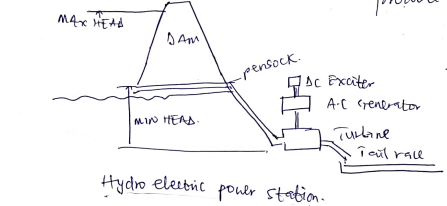
a. Explain what is a ‘prime mover’ and how Hydroelectric power station operates (You may use figures for proper illustration)
b. Briefly explain the three main classifications of Hydro-electric power heads.
a.
A prime mover is a machine component that convert thermal, electrical energy or energy from pressure into mechanical form. Turbines are typical example.
Hydroelectric power station
Hydroelectric power station converts the energy of a moving water into electrical energy by the means of turbine coupled to a generator.
Hydro energy can be extracted from water. Flowing at the lower section of dams, where the pressure forces water to flow. The energy drives a turbine that produces rotation. At the end of the turbine is an alternator that produce electricity.
b.
High Head Development: These have heads in excess of 300m. They use high speed turbines and are found in mountainous regions.
Medium Head Development: Have heads between 30m and 300m and are typically fed from dams on dikes. They use medium speed turbines.
Low Head Development: These have heads under 30m and use low speed turbines.These generation station often extract energy from flowing rivers.
Define Renewable energy and explain how the sun directly and/or indirectly effects generation of electricity from various renewable sources.
Renewable energy is a form of energy that can be replenish (renewed) naturally. Most renewable energy either come directly or indirectly from the sun. Solar energy can be used directly to generate electricity. The sun heat also dives the wind, which can be used to generate electricity using wind turbine. The sun’s heat and winds cause water to evaporate, this then comes down again as the rain which is the main source of water that made up hydroelectric power system. Sunlight causes plant to grow, Biomass can be extracted from those plants.
Some renewable energy sources include:
- Hydro electricity
- Bio fuels
- Wind
- Photo Voltaic
- Geothermal
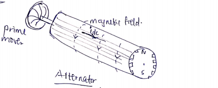
a. Explain the significance of alternators in electricity generation (use figures for proper illustration)
b. With the aid of a suitable diagram describe the main components found in typical distribution substation.
a.
 The alternator converts rotary mechanical energy into electrical energy by creating flux around conductors wound on it. It is coupled to a prime mover e.g a turbine that provides the alternator with mechanical energy.
b. The main component found in distribution substation include:
- Transformers
- Pous bais
- Switching apparatus
- Supply line etc.
Distribution substation is connected to a sub transmission system via supply lines. A supply line can be overhead line or underground feeder.
Transmission typically step-down supply line voltage to distribution level voltage. Distribution substation usually employs three phase transformers.
Busbar carry large current and distribute current to multiple circuit within switchgear or equipment.
Switching apparatus connect or disconnect elements of the power system. They include switches, fuses, circuit breaker and service protectors.
a. Explain why high-voltage transmission lines are used?
b.Identify the common electric power system transmission voltage classes
c. Evaluate the following:
- A 22 kV, 500 MVA star connected 3 phase synchronous generator supplies 450 MW of real power. What is its rated current, the maximum reactive power output and the power factor at maximum output of reactive power.
- A 22 kV 3 phase synchronous generator supplies 415V 3 phase load of 60 kW with a 0.6 power factor, via an ideal three phase step down transformer. Both primary and secondary windings of the transformer are delta connected. What are the transformer primary and secondary phase current amplitudes?
a.
High voltage transmission lines are used because they are more efficient in transporting power over long distance I2R losses will be low since the current is low as the voltage is high,
b.
- Low voltage 0 – 600v
- Medium voltage 600v – 69kv
- High voltage 69 – 230kv
- Extra High voltage 230 – 1100kv
- Ultra High voltage 1100kv
c.
ii) v=22k S=500MVA P=450MW Ir=? Q_(2 max)=? p.f=?
Irated=Srated/(√3 Vrated )
Irated=(500× 106)/(√3×103 ) Irated=13.12KA
S2=P2+Q2
Q=√(S2-P2 )==√(5002-4502 )
Qmax=218MVAr
p.f factor at Qmax
S = P + jQ
∅=tan-1(Q/P) = tan-1(218/450) = 25.80
cos∅=cos 25.9 =0.9
ii) V=22kv
P=√3 VLine Iphase PLoad=SLoad cos∅
S = P + jQ P = S cos∅
I = SLoad/(√3×22×103 )
I1=2.6A (Primary side)
I2=(100×103)/( √3 × 415 ) I2=139A (Secondary side)
a. Discuss the importance of per unit systems in system analysis
b. Explain the limiting factors of generator load angle for electrical generator power stability and how voltage control can improve the stability limits
c. Why are series capacitors often installed on very long AC lines and what advantage do they often have at high geographical altitudes.
a.
Per unit quantity helps simplify network analysis since all impedances of a given equivalent circuit can be added directly.
- It eliminates (root 3) multiplications and divisions
- It provides ease of comparison between different electrical apparatus.
b.
Generator output power
= EVsinδ/X
But stability is limited to
δ = π/2 or dp/dδ < 0
Machine will accelerate as mechanical power becomes constant.
Voltage control such that E α 1/ sinδ can improve stability beyond δ = π/2 which is limited only by Emax
c.
In situations where voltage support is problematic , capacitor banks can be used to increase the reactive power at a system bus to return voltage level to nominal operating values. This method of increasing reactive power support is often used to minimize voltage support problems and improve system stability.
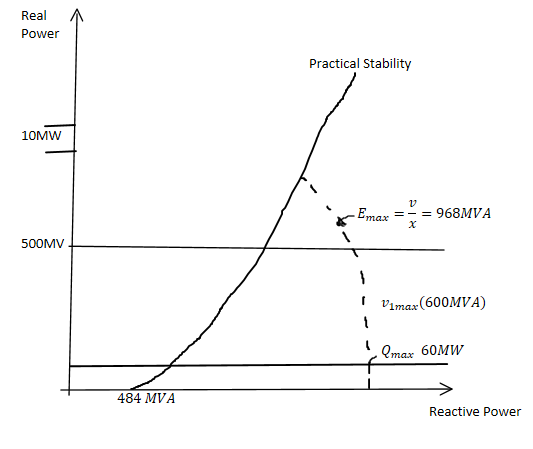
A 22 kV, 600 MVA, star connected 3 phase synchronous generator has a reactance 1.0 Ohms per phase, a maximum open circuit voltage of 44kV and a maximum input mechanical power from the turbines of 500MW. Also include a stability margin of 10MW.
a. Draw the machine operating chart of the above machine. 10 marks
b. What is the maximum and minimum reactive power output at 60MW output power from the machine described in 7A.
c. Two 300 MVA generators have a minimum load of 100MW and their running costs are given by;
F1 = 0.01P12 + 3.2P1 + 20
F2 = 0.02P12 + 2P1 + 10
.
S=600MVA
V=22KV
X= 1ohm p/phase
Voc=44KV
Pin=500MV
10MW stability margin b.
b.
S=√(P2+Q2 ) Q=√(S2– P2 )
S=600MVA P=60MW
Qmax=√(6002-602 )=√(360000 – 3600) = 597MVAr
c.
F1=0.01P12 + 3.2P1+20
F2=0.02P22+2P2 + 10
P1 + P2=PTotal=210
Differentiating F with respect to P
(dF1)/(dP1 )=0.02P1 + 3.2
(dF2)/(dP2 )=0.04P2 + 2
To find the economic, we let
(dF1)/(dP1 )=(dF2)/(dP2 )
0.02P1+3.2=0.04P2 + 2
0.04P2 – 0.02P1 =1.2…………(i)
P1 + P2 = 210……………………(ii)
50 × eqn(i) -P1+ 2P2 = 60……(iii)
Solving eqn (ii) and (iii)
3P2=270 P2=90MW <100MW i.e minimum load
From (ii) we choose P1=210 P2=0
FTOTAL=0.01(210)2 + 3.2(210) + 20 = 1133
for (iii) we choose P1=110 P2=100
FTOTAL=0.01(110)2 +3.2(110) + 20+0.02(100)2 + 2(100) + 10 = 903
Thus P1=110 and P2=1 is the most economic
Credits
Disclaimer
This entire solution may not be 100% accurate, any mistake or typo found should be reported to SmartBukites Management through the following email [email protected] »
All the custom solutions are written for individual research and reference ONLY. SmartBukites does not promote plagiarism in any form and firmly believes that Student will use the solutions models in their individual efforts.
Do you have a Question to Ask?
SmartBukites have a Facebook Group which allows everyone to ask, answer and seek academic help. At SmartBukites, we believe Smart approach to Education will go along way in easing human academic struggle.
Click the link to join now!!! https://web.facebook.com/groups/675122219621351
