a. (i) Differentiate between statics and kinematics.
(ii) Determine the external reaction for simply supported beam shown figure Q1 a.
b. Classify the trusses shown in figure Q1b below as stable, unstable, statically determinate, or statically indeterminate. The trusses are subjected to arbitrary external loading’s that are assumed to be known and can act anywhere on the trusses.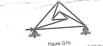
c. Explain the following points and sections on the stress-strain curve for mild steel shown in figure Q1c.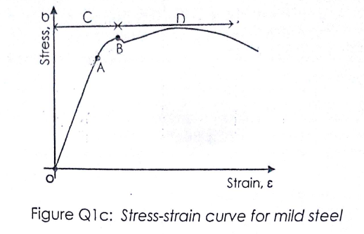
i. Point A
ii. Point B
iii. Section OA
iv. Section AB
v. Section C and
vi. Section D
a. (i) Statics is a branch of mechanics which deals with analysis of loads and their effect on a system which it’s acceleration is 0 m/s2 or it’s relative motion is zero (stationary)
While;
Kinematics is a branch of mechanics which deals with the study of relative motion between various components of a system without considering the forces that cause the motion.
ii. Converting the UDL to point load
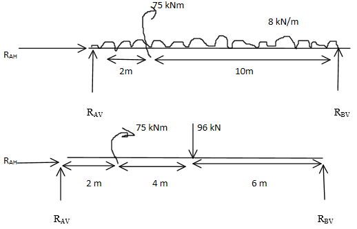
∑MA = 0
-75-(96×6) + (RBV ) = 0
12RBV = 651
RBV= 651/12 = 54.25 KN (↑)
∑ Fy =0 ↑+.
RAV + RBV – 96 = 0
RAV = 96 – 54.25
=41.75 (↑)
∑Fx =0
RAH=0 kN
b) 
No of unknown reactions = 3
No of equations for equilibrium = 3
Therefore the truss is stable.
No of members (m)= 9
No of joints (j)= 6
No of unknowns (r)= 3
Total number of unknowns= m+r = 9+3= 12
Equilibrium equation at each joint= 2j = 2×6= 12.
Since m+r= 2j the truss is statically determinate.
c. 
(i) point A is the limit of proportionality
This is the maximum point at which the deformation of steel will be temporary. That is after withdrawal of the force, the steel will return to it’s original shape. After stress and strain will not be proportional.
(ii) point B is elastic limit.
Beyond this point, if the force is increased then plastic deformation will start.
(iii) Section OA is the modulus of elasticity.
In this region, the straight line in the stress-strain graph shows that stress is proportional to strain.
(iv) Section AB
In this section stress and strain are not proportional to each other but elastic limits not exceeded
(v) section C is the elastic region
Within this region deformation of steel will be temporary.
(vi) Section D is plastic region
At this region plastic deformation will occur and we will have upper yield point and lower yield point. Further increase in force will lead to breaking point.
Also, in this region the material will not return to it’s original shape after withdrawal of force.
a. (i) Differentiate between statics and kinematics.
(ii) Determine the external reaction for simply supported beam shown figure Q1 a.
b. Classify the trusses shown in figure Q1b below as stable, unstable, statically determinate, or statically indeterminate. The trusses are subjected to arbitrary external loading’s that are assumed to be known and can act anywhere on the trusses.
c. Explain the following points and sections on the stress-strain curve for mild steel shown in figure Q1c.
i. Point A
ii. Point B
iii. Section OA
iv. Section AB
v. Section C and
vi. Section D
a. (i) Statics is a branch of mechanics which deals with analysis of loads and their effect on a system which it’s acceleration is 0 m/s2 or it’s relative motion is zero (stationary)
While;
Kinematics is a branch of mechanics which deals with the study of relative motion between various components of a system without considering the forces that cause the motion.
ii. Converting the UDL to point load
∑MA = 0
-75-(96×6) + (RBV ) = 0
12RBV = 651
RBV= 651/12 = 54.25 KN (↑)
∑ Fy =0 ↑+.
RAV + RBV – 96 = 0
RAV = 96 – 54.25
=41.75 (↑)
∑Fx =0
RAH=0 kN
b) 
No of unknown reactions = 3
No of equations for equilibrium = 3
Therefore the truss is stable.
No of members (m)= 9
No of joints (j)= 6
No of unknowns (r)= 3
Total number of unknowns= m+r = 9+3= 12
Equilibrium equation at each joint= 2j = 2×6= 12.
Since m+r= 2j the truss is statically determinate.
c. 
(i) point A is the limit of proportionality
This is the maximum point at which the deformation of steel will be temporary. That is after withdrawal of the force, the steel will return to it’s original shape. After stress and strain will not be proportional.
(ii) point B is elastic limit.
Beyond this point, if the force is increased then plastic deformation will start.
(iii) Section OA is the modulus of elasticity.
In this region, the straight line in the stress-strain graph shows that stress is proportional to strain.
(iv) Section AB
In this section stress and strain are not proportional to each other but elastic limits not exceeded
(v) section C is the elastic region
Within this region deformation of steel will be temporary.
(vi) Section D is plastic region
At this region plastic deformation will occur and we will have upper yield point and lower yield point. Further increase in force will lead to breaking point.
Also, in this region the material will not return to it’s original shape after withdrawal of force.
a. (i) State any four methods used for the analysis of simple trusses.
(ii) Outline any four procedure to analyse a simple truss using method of joint.
b. Determine the forces in the member CD, CF and EF in the Pratt truss shown in figure Q2. Use method of section.
a.
(i) Method of joint
Method of section
Method of tension coefficient
Graphical method of solution
(ii)
- Start with a joint that has not more than two unknown forces
- Establish x and y axis
- At this joint and , calculate the unknown
- After finding the unknown forces applied on this joint, these force become the given value in the analysis of the next joint.
b.
∑Fx = 0
RAH + 3 = 0 ↔ RAH = -3 kN
∑Fy=0
RAH + RBV -5 -10 = 0
RAH + RBV =15…………(1)
∑MA = 0,
-3(1) – 5(8) – 10(5) + RBV (8) = 0
8RBV = 68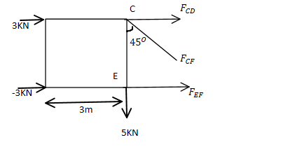 RBV = 8.5 kN
From equation (1)
RAV =15 – 8.5 = 6.5 kN
∑MC=0,
-3(1) – 6.5(3) – FEF (1) = 0
FEF = 22.5 kN (→)
∑Fx = 0,
3 – 3 + FCD + FEF + FCF sin 45o = 0
FCD + FCF sin 45o = -22.50 ……..(1)
∑Fy=0,
6.5-5 – FCF sin 45o =0
FCF sin 45o =1.50
FCF =2.12 kN
From equation (1)
FCD =-22.5 – 2012 sin 45 = -24 kN
A 25 mm diameter bar is subjected to an axial load of 100 kN. Under the action of this load a 200 mm guage length is found to extend 0.19 mm
i. Determine the modulus of elasticity for the bar material
ii. If, in order to reduce weight while keeping the external diameter constant, the bar is bored axially to produce a cylinder of uniform thickness, what is the maximum diameter of bore possible given that the maximum allowable stress is 240 MN/m2? The load can be assumed to remain constant at 100 kN.
iii. What will be the change in the outside diameter of the bar under the limiting stress quoted in (ii)? (E= 210 GN/m2 and v=0.3).
i)
D= 25 mm, F= 100 kN, L= 200 mm and x= 0.19 mm.
A = (πd2)/4 = (π×(25× 103 )2)/4 = 4.9 × 10⁻⁴ m2
E=σl/x
σ= F/A = (10×103)/(4.9 × 10-4 ) = 203.7 × 10⁶ N/m2
E=(203.7× 106 × (200× 10-3))/(0.19 × 10-3 ) =214.44 GN/m2
ii)
Given D= 25 mm, d= ? σ= 240 MN/m2, F= 100 kN
A=(πD2)/4 – (πd2)/4 = (π(D2-d2))/4
σ = F / [(π(D2 – d2)/4]
F=(σπ/4) (D2 – d2)
D2 – d2=F/(σπ/4)
d2=D2-F/(σπ/4)
=(25× 10-3 )2 – [(100 × 103)/(π/4 × 240 ×106 )] =9.448 × 10⁻⁵
d=√(9.448 × 10⁻⁵ ) = 9.72 mm
iii) Given E= 210 GN/m2 and v= 0.3, σ= 240 MN/m2
From;
V = lateral deformation/longitudinal deformation = ϵl/ϵμ
E=σ/ϵμ
ϵμ=σ/E = (240 × 106)/(210 × 109 ) = 1.14 × 10⁻³ϵl=(D2 – D1)/D2 = ∆D/D1
From v = ϵl/ϵμ
ϵl = v × ϵμ= 0.3 × 1.14× 10-3= 3.4310 -4
∆D = ϵl × D1 = 3.43 × 10-4 × 25 × 10-3 =8.57 × 10⁻⁶ m
a)
(i) Explain with the aid of neat sketches, circumferential and longitudinal stresses in thin walled pressure vessels.
(ii) A shell 3.25 m long and 1 m diameter, is subjected to an internal pressure of 1.2 N/mm2. If the thickness of the shell is 10 mm find the circumferential and longitudinal stresses.
b) Show that for a member subjected to shear stress τ, there exist an equal but opposite complimentary shear stress (τ’).
i.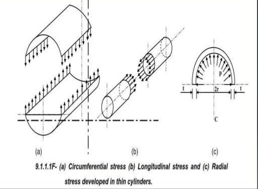
circumferential and longitudinal stresses in thin walled pressure vessels
ii.
D= 1m= 1000 mm, p= 1.2 N/mm2, t= 10 mm, and L= 3.25 m= 3250 mm
longitudinal stress = σl = pd/4t = (1.2×1000)/(4×10) = 30 N/mm2
circumferential stress = σH = pd/2t = (1.2×1000)/(2×10) = 60 N/mm2
b)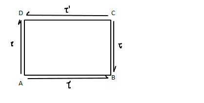
(Shear stress and Complementary shear stress)
Couple produced by τ
(τ BC) × AB
Couple produced by τ’
(τ’ CD) × BC
For equilibrium
(τ BC) × AB= (τ’ CD) × BC
τ = τ’ (AB=CD)
a) State any two application of trusses.
b) Draw the shear force diagram and bending moment diagram and determine maximum bending moment for the beam shown in figure Q5.
a)
- Trusses are used in buildings, mainly where there is a requirement for long spans.
- They are used to carry heavy loads and are sometimes used as transfer structures.
b)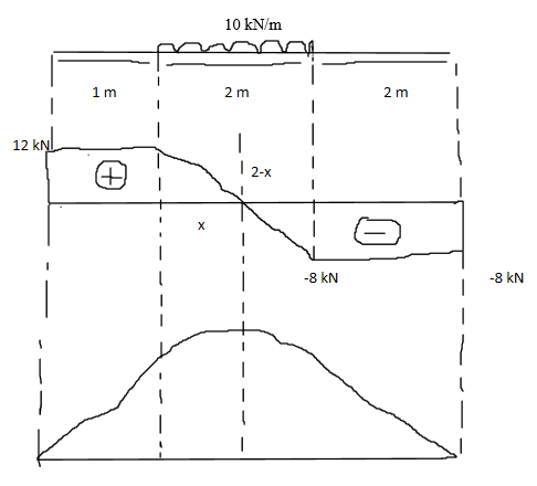
Reactions
∑MA =0, 5RB = (10×2) × 2
RB=40/5 = 8 kN
∑Fy =0,
RA+ RB = 10 × 2
RA = 20 – 8 = 12 kN
Shear force
σFA = RA = 12 kN
σFC =12 kN
σFD =12- (10×2) = -8 kN
σFB =-8 + 8= 0 kN
Bending moment (left to right)
BMA = BMB = 0 kNm
BMC= 12×1 = 12 kNm
BMD = (12×3) – ((10×2) ×1) = 36-20 = 16 kNm
Maximum bending moment at M
x/12 = (2-x)/8
8x = 24 – 12x
24 = 20x
x = 24/20 =1.2 m
Taking moment at M
(12 × (1+1.2)) – (10 × 1.2 × 1.2/2) = 19.2 kNm
a. (i) With the aids of simple diagram mention any six type of supports or connection used to support the structural elements.
(ii) What do you understand by mechanics
b. Describe the nature of normal, shear and bending stresses on a cross section of a member (use neat sketches where applicable).
a.
(i)
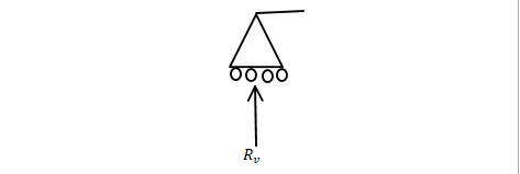
- Roller
Roller (Vertical movement is restricted)
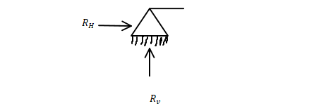
- Hinge
Hinge (Vertical and Horizontal movement is restricted)
- Fixed
Fixed( All movements are restricted)
(ii)
Mechanics is the area of science concerned with the behavior of physical bodies when subjected to forces or displacements, and the subsequent effects of the bodies on their environment.
b.
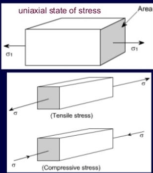
- Normal stresses are stresses that are normal to the area concerned. They are classified into two; tensile stress and compressive stress.
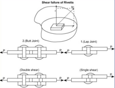
- Shear stresses is a stress that cause a deformation of a material by slippage along a plane or planes parallel to the imposed stress.
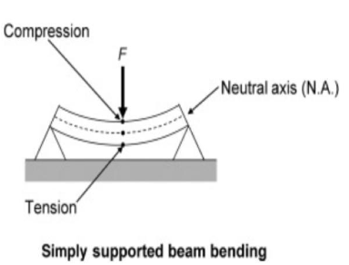
- Bending stress is a normal stress that is induced at a point in a body subjected to loads that cause it to bend. When a load is applied perpendicular to the length of a beam (with two supports on each end), bending moments are induced in the beam.
Do you have a Question to Ask?
SmartBukites have a Facebook Group which allows everyone to ask, answer and seek academic help. At SmartBukites, we believe Smart approach to Education will go along way in easing human academic struggle.
Click the link to join now!!! https://web.facebook.com/groups/675122219621351
